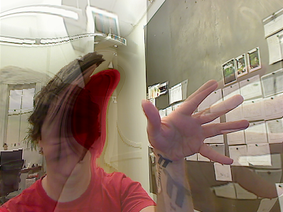
Pictured: Interactive input and GPU techniques combine to warp live video The key to making fast visuals is getting as much of your data and logic onto your video card as possible. This keeps it closer to where it needs to be in your hardware, freeing your computer's CPU and memory to do other things. At the core of this technology is GPGPU, or general purpose computing on the GPU. That is, the ability to store and process non-graphic data on your video card. This tutorial explains what is involved in GPGPU, the FBO ping pong technique, and what you can do with it. The sample project uses Cinder and OpenGL. I recommend downloading the source first. Build the project and watch it run. Then go through the code with this tutorial for an explanation on why it works the way it does. SOURCE ON GITHUB Open the "GpGpu" sample in BTR-Tutorials Let me explain a few terms you'll see a lot in this tutorial. FRAME BUFFER OBJECT (FBO) A frame buffer object (FBO) is essentially a chunk of memory on your video card which holds data. When you draw graphics to your screen, you are actually writing color data to a default FBO which sends data to an output. However, you can create custom FBOs to store data. This data is called a "texture". The data in this texture can be read using a shader. A FBO can be thought of as a "render target". When you "bind" a custom FBO, anything you draw will render to it. Without a custom FBO bound, drawing commands are sent to the default FBO, which appears on your monitor. SHADER (GLSL) OpenGL shaders are applications written in GLSL , a C-like language. GLSL is compiled in your C++ application and load onto the video card. Cinder will do this for you. A shader application is run against each element it's targeting. A vertex shader is executed against the vertices in your shape. A fragment shader is executed on each, well... fragment. For our purposes, we are drawing a single full screen quad and working almost entirely in the fragment shader. A fragment is not the same as a pixel, but we'll essentially treat them as the same thing here. PING PONG The basic idea of the "ping pong" technique is that you have two FBOs with at least one texture. You read the texture from one FBO, then run a shader program to draw the output to the other FBO. Use the texture from the render target as input for rendering graphics. On the next frame, you'll use the texture in the FBO onto which you just drew as the data source. The result is that you can store and process data without writing any code in the CPU realm. CPU vs GPU The "CPU" realm refers to code which is executed on your machine's CPU and memory. Your video card is like a special, purpose-built computer inside your computer. It has its own CPU, called the GPU, and its own memory. Anything executed there is referred as the "GPU" side of your machine. Mouse input is processed on the GPU using the FBO ping pong method, producing an image which is used to refract a texture. See what the raw data looks like at the 5s mark. CODE This sample implements a GLSL version of the classic 2D water algorithm. The basic idea is that you have two FBOs, a GPGPU shader to process the water animation, an image to refract, and another shader to refract the image. Let's analyze the code in six distinct parts. 0. HEADER Let's take a look at our application's header file ("GpGpuApp.h") to see how we declare what we need in Cinder. #pragma once #include "cinder/app/AppBasic.h" #include "cinder/gl/Fbo.h" #include "cinder/gl/GlslProg.h" #include "cinder/gl/Texture.h" class GpGpuApp : public ci::app::AppBasic { public: void draw(); void keyDown( ci::app::KeyEvent event ); void mouseDown( ci::app::MouseEvent event ); void mouseDrag( ci::app::MouseEvent event ); void mouseUp( ci::app::MouseEvent event ); void prepareSettings( ci::app::AppBasic::Settings *settings ); void setup(); private: // Convenience method for drawing fullscreeen rectangle // with texture coordinates void drawFullScreenRect(); // Frame buffer objects to ping pong ci::gl::Fbo mFbo; size_t mFboIndex; // Shaders ci::gl::GlslProg mShaderGpGpu; ci::gl::GlslProg mShaderRefraction; // Refraction texture ci::gl::Texture mTexture; // Mouse ci::Vec2i mMouse; bool mMouseDown; // True renders input to screen bool mShowInput; }; We start by including the files from Cinder we'll need to define our application, the FBOs, texture, and shaders. The application class is declared, complete with member properties and Cinder callbacks. The "mFbo" array contains two of Cinder's FBOs. "mFboIndex" indicates which FBO we are using as the data source (this is always 0 or 1). There are two shaders, one for GPGPU and one for refraction. We have a texture to refract, named "mTexture". We also have properties for tracking mouse input and toggling the draw mode. GPGPU is usually accomplished by drawing a 2D quad with texture coordinates. The method "drawFullScreenRect" will help us do that. 1. IMPLEMENTATION Now let's move into the implementation ("GpGpuApp.cpp"). #include "GpGpuApp.h" #include "cinder/ImageIo.h" #include "Resources.h" using namespace ci; using namespace ci::app; using namespace std; const Vec2i kWindowSize = Vec2i( 700, 700 ); const Vec2f kPixel = Vec2f::one() / Vec2f( kWindowSize ); Include the application header and the files we'll need to load our shaders and refraction image. We include these files here instead of in the header to reduce compile time. Rather than reviewing the "Resources.h" file here, go ahead and open it to check out how Cinder sets up resources. Next, we make a few "using" statements so we don't have to write fully qualified names when declaring variables. Then we define two constants which we'll use to establish the dimensions of our window and data buffer. "kPixel" is the size of one pixel using the [0,0]-[1,1] coordinate space we use in GLSL. 2. SETUP On to the application setup... void GpGpuApp::prepareSettings(Settings *settings) { settings->setWindowSize( kWindowSize.x, kWindowSize.y ); settings->setFrameRate( 60.0f ); settings->setResizable( false ); } void GpGpuApp::setup() { // Set flags mMouse = Vec2i::zero(); mMouseDown = false; mShowInput = false; // Load shaders try { mShaderGpGpu = gl::GlslProg( loadResource( RES_PASS_THRU_VERT ), loadResource( RES_GPGPU_FRAG ) ); } catch ( gl::GlslProgCompileExc ex ) { console() << "Unable to compile GPGPU shader:\n" << ex.what() << "\n"; quit(); } try { mShaderRefraction = gl::GlslProg( loadResource( RES_PASS_THRU_VERT ), loadResource( RES_REFRACTION_FRAG ) ); } catch ( gl::GlslProgCompileExc ex ) { console() << "Unable to compile refraction shader:\n" << ex.what() << "\n"; quit(); } // Load refraction texture { gl::Texture::Format format; format.setInternalFormat( GL_RGBA32F_ARB ); mTexture = gl::Texture( loadImage( loadResource( RES_TEXTURE ) ) ); mTexture.setWrap( GL_REPEAT, GL_REPEAT ); } // Create FBO { // Set up format with 32-bit color for high resolution data gl::Fbo::Format format; format.enableColorBuffer( true ); format.enableDepthBuffer( false ); format.setColorInternalFormat( GL_RGBA32F_ARB ); // Create two frame buffer objects to ping pong mFboIndex = 0; for ( size_t n = 0; n < 2; ++n ) { mFbo[ n ] = gl::Fbo( kWindowSize.x, kWindowSize.y, format ); mFbo[ n ].bindFramebuffer(); gl::setViewport( mFbo[ n ].getBounds() ); gl::clear(); mFbo[ n ].unbindFramebuffer(); mFbo[ n ].getTexture().setWrap( GL_REPEAT, GL_REPEAT ); } } } CINDER_APP_BASIC( GpGpuApp, RendererGl( RendererGl::AA_MSAA_32 ) ) In the "prepareSettings" method, we set our application's window size and frame rate. "setup" initializes flags and the mouse position. Always define properties you declare as soon as you can so you don't end up trying to use or evaluate bad or undefined data. Cinder has a nice way of loading shaders which throws an exception if it fails. This exception contains debug data, telling you exactly which errors occurred and where. Then we load the refraction texture, a nice little photo I took at the Upper Geyser Basin in Yellowstone . And finally we set up the FBOs. Note that the color format is set to 32-bit RGBA. This gives us four channels of 32-bit floating point data to work with. The higher resolution will give us more precise data and smoother animation than the default 8-bit. The FBOs are cleared to zero each pixel. Their textures are made to repeat (loop) at the edges. The "CINDER_APP_BASIC" macro creates the application. Note that the renderer is told to use "AA_MSAA_32" anti-aliasing. This will make the rendered image nice and smooth. 3. INTERACTIVITY Now let's look at how we track mouse movement. void GpGpuApp::mouseDown( MouseEvent event ) { mMouseDown = true; mouseDrag( event ); } void GpGpuApp::mouseDrag( MouseEvent event ) { mMouse = event.getPos(); } void GpGpuApp::mouseUp( MouseEvent event ) { mMouseDown = false; } All we're doing here is using the Cinder mouse callbacks to record the cursor position and whether or not the button is being pressed. Let's add some keyboard input. void GpGpuApp::keyDown( KeyEvent event ) { switch ( event.getCode() ) { case KeyEvent::KEY_q: quit(); break; case KeyEvent::KEY_i: mShowInput = !mShowInput; break; } } Now you can press "q" to quit and "i" to toggle the refraction shader pass. 4. GPGPU Now we can get into the meat of the process in the "draw" method. This is divided into two shader passes, both of which are processed by the "drawFullScreenRect" method. Let's break this down into a few parts. void GpGpuApp::draw() { /////////////////////////////////////////////////////////////// // GPGPU pass // Enable textures gl::enable( GL_TEXTURE_2D ); gl::color( Colorf::white() ); // Bind the other FBO to draw onto it size_t pong = ( mFboIndex + 1 ) % 2; mFbo[ pong ].bindFramebuffer(); // Set up the window to match the FBO gl::setViewport( mFbo[ mFboIndex ].getBounds() ); gl::setMatricesWindow( mFbo[ mFboIndex ].getSize(), false ); gl::clear(); // Bind the texture from the FBO on which we last // wrote data mFbo[ mFboIndex ].bindTexture(); // Bind and configure the GPGPU shader mShaderGpGpu.bind(); mShaderGpGpu.uniform( "buffer", 0 ); mShaderGpGpu.uniform( "pixel", kPixel ); // Draw a fullscreen rectangle to process data drawFullScreenRect(); // End shader output mShaderGpGpu.unbind(); // Unbind and disable textures mFbo[ mFboIndex ].unbindTexture(); gl::disable( GL_TEXTURE_2D ); // Draw mouse input into red channel if ( mMouseDown ) { gl::color( ColorAf( 1.0f, 0.0f, 0.0f, 1.0f ) ); gl::drawSolidCircle( Vec2f( mMouse ), 5.0f, 32 ); gl::color( Color::white() ); } // Stop drawing to FBO mFbo[ pong ].unbindFramebuffer(); // Swap FBOs mFboIndex = pong; ... The draw command kicks off by enabling OpenGL textures and setting the color to white. We set the color to white to keep values from accidentally being interpolated to something we don't want. "mFboIndex" indicates which FBO we are using as input. We create a variable named "pong" as the index for the other FBO which bind as the render target. Whenever you set a new render target, make sure to update your viewport to match its dimensions. In this example the window and "offscreen" FBOs are the same size, but I still set the viewport in case I ever want to change the size of the window or data FBO. Then we bind the "ping" FBO's texture so we can use it as a data source in the GPGPU shader. It is automatically bound to ID 0 unless specified otherwise. We bind the GPGPU shader and set two "uniforms". Uniforms are global variables in GLSL which you can set from the CPU realm. Any drawing code executed while a shader is bound is processed by the shader. We want to use every pixel on screen, so we draw a fullscreen quad. We'll look at the shader in a moment, but for now trust that it just processed data from the last frame. We then unbind the shader and disable textures so we can draw new input into the render target. The GPGPU shader stores height data in the red channel. If there is mouse input, we can add it to the data by drawing a red circle while the render target FBO is still bound. Finally, we unbind the render target FBO. This switches the render target back to the screen. "mFboIndex" is swapped with the index of the render target, which we will now use as input. Let's take a look at what happened in that shader pass. We drew a full screen quad to be processed by the shader using the "drawFullScreenRect" method. void GpGpuApp::drawFullScreenRect() { // Begin drawing gl::begin( GL_TRIANGLES ); // Define quad vertices Area bounds = getWindowBounds(); Vec2f vert0( (float)bounds.x1, (float)bounds.y1 ); Vec2f vert1( (float)bounds.x2, (float)bounds.y1 ); Vec2f vert2( (float)bounds.x1, (float)bounds.y2 ); Vec2f vert3( (float)bounds.x2, (float)bounds.y2 ); // Define quad texture coordinates Vec2f uv0( 0.0f, 0.0f ); Vec2f uv1( 1.0f, 0.0f ); Vec2f uv2( 0.0f, 1.0f ); Vec2f uv3( 1.0f, 1.0f ); // Draw quad (two triangles) gl::texCoord( uv0 ); gl::vertex( vert0 ); gl::texCoord( uv2 ); gl::vertex( vert2 ); gl::texCoord( uv1 ); gl::vertex( vert1 ); gl::texCoord( uv1 ); gl::vertex( vert1 ); gl::texCoord( uv2 ); gl::vertex( vert2 ); gl::texCoord( uv3 ); gl::vertex( vert3 ); // End drawing gl::end(); } Triangles are the foundation of geometry in OpenGL. This method creates a rectangle by drawing two adjacent triangles. Each corner of the triangles are defined as vertices which can contain a few types of data GLSL will understand. Here, we are only setting the position and texture coordinate of each vertex. The texture coordinates, which must be between 0.0 and 1.0, will allow us to tell which pixel is being rendered in GLSL. Each vertex is processed by a vertex shader. When doing GPGPU, we will generally use what is called a "pass-through" vertex shader ("passThru_vert.glsl"). All that this type of shader does is pass data to the fragment shader without modifying the vertex. varying vec2 uv; void main( void ) { uv = gl_MultiTexCoord0.st; gl_Position = gl_ModelViewProjectionMatrix * gl_Vertex; } "uv" is a common name for "texture coordinate". This property is a "varying", meaning it can be shared between shaders. OpenGL interpolates data between vertices by dividing it into "fragments". The fragment shader sets the color for each of these pieces. In our draw command, we told OpenGL to set the matrices to match the window. The window is 700x700, so OpenGL will basically fragment our quad into a 700x700 grid. Or 700x700 pixels. 5. 2D WATER The GPGPU fragment shader ("gpgpu_frag.glsl") in this sample emulates 2D water by reading height data from the red channel and velocity data from the green channel. Fragment shaders can read data from textures. In this case, we're using the texture from the other FBO as input. Each fragment looks up values in the corresponding input texture to come up with new data. uniform sampler2D buffer; // Data texture uniform vec2 pixel; // Size of a pixel in [0,0]-[1,0] varying vec2 uv; // Texture coordinate const float dampen = 0.993; // Ripple dampening const float power = 1.5; // Input power const float speed = 1.0; // Ripple travel speed // Samples velocity from neighbor float getSpring( float height, vec2 position, float factor ) { return ( texture2D( buffer, position ).r - height ) * factor; } void main( void ) { // Kernel size vec2 kernel = pixel * speed; // Sample the color to get the height and velocity of this pixel vec4 color = texture2D( buffer, uv ); float height = color.r; float vel = color.g; // Sample neighbors to update this pixel's velocity. Sampling inside of for() loops // is very slow, so we write it all out. vel += getSpring( height, uv + kernel * vec2( 2.0, 3.0 ), 0.0022411859348636983 * power ); vel += getSpring( height, uv + kernel * vec2( 0.0, 3.0 ), 0.0056818181818181820 * power ); vel += getSpring( height, uv + kernel * vec2( -2.0, 3.0 ), 0.0022411859348636983 * power ); vel += getSpring( height, uv + kernel * vec2( 2.0, 2.0 ), 0.0066566640639421000 * power ); vel += getSpring( height, uv + kernel * vec2( 0.0, 2.0 ), 0.0113636363636363640 * power ); vel += getSpring( height, uv + kernel * vec2( -2.0, 2.0 ), 0.0066566640639421000 * power ); vel += getSpring( height, uv + kernel * vec2( 3.0, 1.0 ), 0.0047597860217705710 * power ); vel += getSpring( height, uv + kernel * vec2( 1.0, 1.0 ), 0.0146919683956074150 * power ); vel += getSpring( height, uv + kernel * vec2( -1.0, 1.0 ), 0.0146919683956074150 * power ); vel += getSpring( height, uv + kernel * vec2( -3.0, 1.0 ), 0.0047597860217705710 * power ); vel += getSpring( height, uv + kernel * vec2( 2.0, 0.0 ), 0.0113636363636363640 * power ); vel += getSpring( height, uv + kernel * vec2( -2.0, 0.0 ), 0.0113636363636363640 * power ); vel += getSpring( height, uv + kernel * vec2( 3.0, -1.0 ), 0.0047597860217705710 * power ); vel += getSpring( height, uv + kernel * vec2( 1.0, -1.0 ), 0.0146919683956074150 * power ); vel += getSpring( height, uv + kernel * vec2( -1.0, -1.0 ), 0.0146919683956074150 * power ); vel += getSpring( height, uv + kernel * vec2( -3.0, -1.0 ), 0.0047597860217705710 * power ); vel += getSpring( height, uv + kernel * vec2( 2.0, -2.0 ), 0.0066566640639421000 * power ); vel += getSpring( height, uv + kernel * vec2( 0.0, -2.0 ), 0.0113636363636363640 * power ); vel += getSpring( height, uv + kernel * vec2( -2.0, -2.0 ), 0.0066566640639421000 * power ); vel += getSpring( height, uv + kernel * vec2( 2.0, -3.0 ), 0.0022411859348636983 * power ); vel += getSpring( height, uv + kernel * vec2( 0.0, -3.0 ), 0.0056818181818181820 * power ); vel += getSpring( height, uv + kernel * vec2( -2.0, -3.0 ), 0.0022411859348636983 * power ); // Update this pixel's height (red channel) height += vel; // Reduce the velocity vel *= dampen; // Store the height and velocity in the red and green channels gl_FragColor = vec4( height, vel, 0.0, 1.0 ); } "buffer" is the texture from the other FBO. "pixel" is the size of a pixel in [0,0]-[1,1] coordinates. "uv" is the texture coordinate for the current fragment. Remember, "uv" was passed here from the vertex shader. Then we define a few const's to control the water animation. Inside the "main" body, we read the buffer at the "uv" with the "texture2D" method. We only need the red and green channels to get height and velocity. Then we read height values from neighbors, adding them to the velocity of the current pixel. The velocity is reduced so the ripples eventually slow down. The new height and velocity values are written to the red and green channels. This makes them available for the next frame. 6. REFRACTION Now we are ready to use our data. The second half of the 2D water technique is refracting an image so it looks like it is under water ripples. Let's look at the second shader pass in the "draw" method. ... /////////////////////////////////////////////////////////////// // Refraction pass // Clear screen and set up viewport gl::clear( Color::black() ); gl::setViewport( getWindowBounds() ); gl::setMatricesWindow( getWindowSize() ); // This flag draws the raw data without refraction if ( mShowInput ) { gl::draw( mFbo[ mFboIndex ].getTexture() ); } else { // Bind the FBO we last rendered as a texture mFbo[ mFboIndex ].bindTexture( 0, 0 ); // Bind and enable the refraction texture gl::enable( GL_TEXTURE_2D ); mTexture.bind( 1 ); // Bind and configure the refraction shader mShaderRefraction.bind(); mShaderRefraction.uniform( "buffer", 0 ); mShaderRefraction.uniform( "pixel", kPixel ); mShaderRefraction.uniform( "tex", 1 ); // Fill the screen with the shader output drawFullScreenRect(); // Unbind and disable the texture mTexture.unbind(); gl::disable( GL_TEXTURE_2D ); // End shader output mShaderRefraction.unbind(); } } Now that we're targeting the main window, we start off by setting the viewport and matrices to match. You can skip the refraction by pressing "i" and see what the raw data looks like. To run the refraction, we bind the texture from the FBO we last rendered and use it as a data buffer. We also bind the image to refract. The rest is the same as the GPGPU pass -- draw a fullscreen rectangle with the shader bound. This pass also uses the pass-through vertex shader, so let's just go through the fragment shader ("refraction_frag.glsl"). uniform sampler2D buffer; // Data texture uniform vec2 pixel; // Size of a pixel in [0,0]-[1,0] uniform sampler2D tex; // Refraction texture (the image to be warped) varying vec2 uv; // Texture coordinate void main( void ) { // Calculate refraction vec2 above = texture2D( buffer, uv + vec2( 0.0, -pixel.y ) ).rg; float x = above.g - texture2D( buffer, uv + vec2( pixel.x, 0.0 ) ).g; float y = above.r - texture2D( buffer, uv + vec2( 0.0, pixel.y ) ).r; // Sample the texture from the target position gl_FragColor = texture2D( tex, uv + vec2( x, y ) ); } The refraction is easy. We read red and green channels from the pixels above and to each side to find out how to warp the refraction texture. REVIEW Let's boil the GPGPU process down to a sequence: Bind FBO A as render target Bind FBO B as input texture Bind GPGPU shader to process input texture Draw any new data Unbind FBO B's texture Unbind GPGPU shader Unbind FBO A to draw to screen Swap FBO A with FBO B The texture in FBO A is now current and ready to use for rendering. WHAT NOW? The FBO ping pong technique is a core principle of GPGPU. If you understand this simple example in its entirety, it should open doors to other processes you can move to the GPU. Here, we used two channels of a texture to store 1D height and velocity data. Try using all four channels to store and process 2D data instead. Much like you can use multiple textures when rendering to your screen, you can work with multiple textures inside of a FBO. These are called "color attachments". Imagine a 3D particle system where each color attachment store a different property of each particle -- RGB channels can represent XYZ data for position, velocity, acceleration, and more. Did you know that your vertex shader can read textures? This is called "vertex texture fetching" (VTF). The Cinder-MeshHelper block includes a VTF sample demonstrating how to use a dynamically generated texture to warp geometry. Try creating the displacement texture with GPGPU techniques for high-performance, dense, interactive visuals.
